


About the Gamelometer
The Gamelometer was designed and manufactured to help answer questions posed by Dr. Andrew McGraw at the University of Richmond. From Andrew McGraw:
This research program deals with those aspects of timing and dynamics that are not learned through explicit instruction, for which their (and our) music cultures do not have specific terminologies other than vague, normative phrases like: feel, swing, time, groove. In Balinese: rasa, selah, pangus.
My first question concerns the 'Byar!;' the opening tutti note of most kebyar works (ie. Kebyar Gandrung). Many Balinese composers suggest that they can identify whether a group is Balinese, or American, or Japanese by hearing this single note. This suggests that it is simply a matter of accurate simultaneity (everyone playing their notes at exactly the same time). However, many composers also suggest that they can identify different, proficient, Balinese regional groups within this single musical moment as well, suggesting that something more complex is happening. I want to get specific timing (relative onset) information for most of the instruments in the gamelan for this single note: 20 sensors could cover each of the key instruments. Dynamic information would be useful as well.
My second question is a more complex field of inquiry. It concerns the microadjustments expert players perform while playing kotekan. Far from being simply an even division of the beat (kajar) into 4 perfectly even subdivisions, successful kotekan more often involves a complex 'lilt' as polos and sangsih players adjust to each other's pushes and pulls in real time. I would want up to 10 sensors for this problem, to cover two gangsa (repeating a static kotekan), two calung and kempli.
Included Components
The Gamelometer: Included components
- 8-channel (x3) piezo-film pre-amp box (24 channels total)
- 24 piezo-film sensors w/BNC connectors
- 24 sensor stabilization boards with interfacing connectors.
- 24 lightweight coaxial interfacing cables to connect sensors to pre-amp boxes
Theory and Operation
How it all works
The device is very similar to a 24-channel microphone pre-amp with the exception that the piezo-film sensors measure vibration of a solid body rather than air pressure. This requires specialized circuitry that is different from conventional microphone pre-amp.
The device uses piezo-film sensors made by Measurement Specialties. These laminated sensors are excellent at converting mechanical work into an electrical signal and are also extremely sensitive. The sensors as so sensitive, though, that if they were hooked up directly to audio recording equipment, they would most likely overload the device and produce results difficult to use.
Figure 1 Charge Mode Amplifier for Piezo-film Sensor
The first stage of the pre-amp (1) converts the electric charge created by the sensor when pressure is applied to a use-able voltage level proportional to the pressure itself. Two things happen in this stage: The voltage is reduced to a range that is more appropriate for audio recording, and the bandwidth of what is passed is set to the audio range of 20Hz-20kHz.
A gain stage is added in stage 2 (2) so that signals can then be appropriately increased and set for various applications, i.e. the recording of different instruments of slightly different dynamic ranges.
Figure 2 Gain Stage
Once the overall gain is set, the signal is conditioned with a high pass filter in stage 3 (3) to even further reduce unwanted noise and information outside of the low-end musical range of interest. This reduces low frequency mechanical noise created by the instrument itself as a function of being played.

Figure 3 - Signal Conditioning High Pass Filter
The final stage is simply signal attenuation made possible by the volume potentiometer provided on the top of the device. This stage is present so that once gains are set it is still possible to reduce signals on a temporary or per recording basis.
Technical notes about the circuit chain: All operational amplifiers are low voltage single supply op amps (TLV2774) so that the device can easily run off of +5V USB power. All devices should run simultaneously on 1 USB supply, but a breakout connector or hub is needed to supply each of the 3 8 channel boxes.

Figure 4 2.5V Voltage Reference and Voltage Follower Buffer
As a result of only using +5V power, the sensor and signal need to have a DC offset voltage applied so that a virtual ground exists at +2.5V. This allows for a positive an negative voltage swing for the audio signal. A bypass capacitor is used prior to output to remove this DC signal, leaving only the AC audio signal remaining. Each channel has it’s own +2.5V DC offset, derived from the +5V USB power supply using a simple voltage divider and buffered by a voltage follower op amp stage.
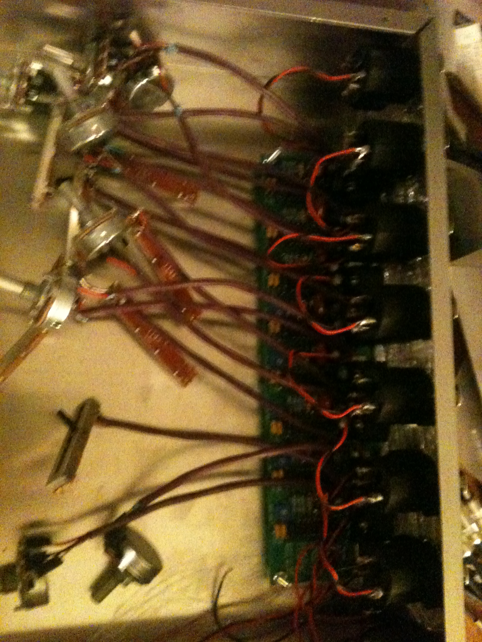
Design & Production Pictures
I've compiled some pictures from the design stage of the PCB itself through fabrication and use in Bali.


Using the Gamelometer

Figure 5 Insert one end of clamp into resonator
Before placing a sensor on a key, mount the sensor stabilization board to the instrument as in Figure 5 by inserting one end of the clamp into the resonating tube. You may need to lift the key a bit to do this. Tighten the clamp.
How a sensor is placed on a surface will directly influence the resulting signal and audio recording. It is important to have as much of the sensor itself in direct contact with the vibrating surface to ensure uniformity in results and consistency across channels.

Experimentation has shown that using Scotch/3M Removable Sticky Square (xxx) provides a good balance between a secure connection that does not overly damp the vibrating body itself and the ease of removing and attaching the sensor. Other adhesives can be too heavy, affecting the vibration itself, or too difficult to remove when the intended session has ended. Some might leave a residue on the keys. Experimentation has also shown that it’s best to keep the associated plastic housing secure so as not to contribute to any unwanted vibration or noise. Trying to place this off of the key entirely or on the node of the key work best. If placing it on the node, be sure to place the 3M sticky paper to the plastic part of the sensor as well. This keeps everything together and also helps damp that plastic a bit. Figure shows one possible ways of connecting the sensor. Press the sensor firmly onto the key to ensure a tight bond. And remember, you’re using the removal pads, so it’ll be easy to take off later. Use new sticky pads for each new attachment of a sensor to a key.

After the sensor is attached to the key, feed the thin cable through the wing nut strain relief system. If possible, make sure the cable sits higher than the sensor itself. The key itself will move quite a bit, so it’s good to not allow the key to hit the cable. Tighten this and than connect the BNC connector. Use a supplied BNC coaxial cable to then connect the stabilization unit to a channel on one of the 8-channel pre-amp boxes.
The device is not meant to be used as a stand alone device and is intended to be interfaced with conventional audio recording or amplification equipment. Each of the 8-channel boxes includes 8 unbalanced audio output channels via a combination XLR/TRS connector. Connect these now. Prior to powering up the device, it’s a good idea to turn down the gain of each channel so as to not overload any connected devices unexpectedly. You are now ready to power on the device. Enjoy.